These
circuits enable two-conductor DC power supplies (including DC wall adapters, 9V and 12V batteries, etc.) to function as split supplies with three conductor
outputs
(i.e., positive, negative AND ground). They are called
"Virtual Grounds" or "Rail Splitters". These
circuits enable two-conductor DC power supplies (including DC wall adapters, 9V and 12V batteries, etc.) to function as split supplies with three conductor
outputs
(i.e., positive, negative AND ground). They are called
"Virtual Grounds" or "Rail Splitters". |
| Adjustable Voltage Regulators |
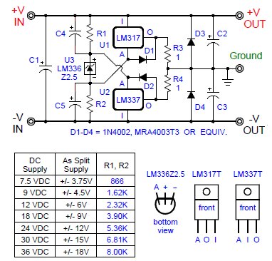
| The
inexpensive LM317/LM337 circuits below are capable of delivering up to
+/-18V
at more than 1.5 amps, 75 times the current of a TLE2426 rail splitter
chip. The DC Supply Input can be from 7.5VDC to 40VDC. The TO-220
voltage
regulators are each rated for 20W. However, they can handle a watt or
more
without heatsinks - example: Output = +/- 9VDC @ 60mA. |
| Both
the LM317/LM337 Basic and VG1 Circuits below
draw
quiescent current of only 4 or 5 milliamps - great for battery use! |
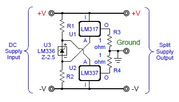
Basic
Virtual Ground
Circuit with Adjustable Voltage Regulators
|
|
| How
it works: The LM317 (positive) and LM337 (negative)
adjustable
voltage regulators operate in parallel with their outputs tied together
through small resistors to create a virtual ground. The LM336BZ-2.5V
voltage
reference compensates for the LM317's (+1.25V) internal reference and
the
LM337's (-1.25V) internal reference. So when the LM317/LM337 adjust
pins
are connected inside the R1/R2 voltage divider as shown, each voltage
regulator
output voltage becomes 1/2 of whatever the rail-to-rail voltage happens
to be. Thus, together, the voltage regulators "split the rails",
creating
a "rock solid" virtual ground. |
| Although
a simple and inexpensive virtual ground solution, some audio designs
sound better when using it. For example, when powering a headphone
amplifier, the bass notes may sound clearer and
more
life like. This could be due to how the voltage regulators hold the ground point firmly in place.
|
|
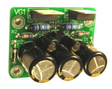
VG1 Virtual
Ground Circuit
|
 |
|
|
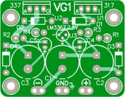
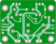
VG1 PC Board (Top)
|
(Bottom) 1.4" x 1.8" |
similar earlier version |
|
|
VG1 PC Boards are available for $5 each. P/N = VG1 Above, at right, an assembled earlier version.
PC Board size: 1.4" x 1.8" Mounting holes are for 4-40 screws, spaced 1.0" x 1.5".
|
All parts are redily available and easy to find - and can be ordered from Mouser.com
or Digikey.com.
Resistor and
capacitor values
are not critical - you can substitute near or alternate values. |
|
VG1 Parts List:
|
notes:
|
| R1,
R2 - see VG1 schematic chart |
1/4W
or 1/2W |
| R3,
R4 - 0.75 ohm to 1 ohm |
1/4W
or 1/2W |
| C1 -
470uF/50V** |
Panasonic
P/N EEU-FM1H471 |
| C2,
C3 - 1000uF/25V** |
Panasonic
P/N EEU-FM1E102 |
| C4,
C5 - 22uF/50V |
Panasonic
P/N EEU-FM1H220 |
| D1 - D4 - 1N4002 (or
similar) |
for SMD: MMRA4003T3
|
| U1 -
LM317T |
TO-220
package Digi-Key, etc. |
| U2 -
LM337T |
TO-220
package Digi-Key, etc. |
| U3 -
LM336Z2.5 |
2.5V
voltage reference (Fairchild) |
|
NOTES:
|
1) The
values for
R1 and R2 shown in the chart above yield about 2mA of current through
the
LM336BZ-2.5V.
The formula used to determine the values is: R1 or R2
= (Vrr - 2.5) / .002 / 2. For example with a 12V power
supply: (12 - 2.5)
/.002 / 2 = 2375.
So use a 2.37K resistor for R1 & R2. Also: I = (DC
supply
- 2.5) / (R1+R2). |
2) The adjust pin
on the LM336 voltage reference is not used, so leave it
unconnected;
only connect
the "+" and
"-" pins. |
3) Reducing
component count: When using a battery for the DC source, such as a 9V
battery in a low current application, you can skip
installing
C1 - C5 and D1 - D4 altogether and simply use the Basic
Circuit
as shown at the top of this page. However, when
powering low-noise audio circuitry and if your DC power supply is
plugged into an AC source, you
should install all of the
capacitors. C1 - C3 can be 2,200uF - 10,000uF more. This necessitates
installing all of the diodes to protect the voltage regulators from the
large discharging capacitors at turn-off.
|
4) A test of the VG1 Circuit was done with an Eveready Gold 9V alkaline battery
as the DC supply, the R1/R2 resistors were each 1.62K, and there was no load on the output of the circuit. The 9V battery itself actually measured 9.3V. Results: The ground remained perfectly centered (+/- 4.65V), while the
total current being drawn was only about 4.5mA. This shows that with
2mA
through the voltage divider section, the rest of the circuit was
consuming
only an additional 2.5mA. And that says if we add a 20mA load to
the output, and if the 9V battery could supply 350mAH to 550mAH, the
battery
would last about 12 to 20 hours or more of continuous use.
|
| 5) You may be able
to reduce the size of the 1 ohm output resistors to 0.75 ohm or less by
minimizing the current through the LM336BZ-2.5 (by using larger value
R1/R2
resistors). A small ground point voltage offset, if it happens, is
usually
acceptable. An LM336BZ-2.5V can operate with 0.5mA to 10mA of forward
current. |
| 6) The LM317/LM337s
require about 1.5 to 6mA of load current to maintain regulation - and
they
will continue to regulate with an Input voltage as low as 3.7
volts. |
| 7) Increasing the
size of C1, C2 and C3 can be sonically advantageous. They can be 220uF
to 12,000uF, (or as much as you can afford or have room for.)
Generally,
electrolytic capacitor rated voltages should be at least 30 percent
higher
than whatever their power supply voltage is. |

|
| If
you are using the virtual ground with an audio circuit and your DC
power
supply has an AC source, adding another voltage regulator in front of
the
rail splitter section can further improve sound quality. An LD1085V,
3A LDO (Low Dropout Voltage) voltage regulator sounds better for this
purpose
than others I've compared by listening tests. When using this
additional
voltage regulator (U4), be sure that your DC Supply (input voltage) is
always 1.5V (or more) higher than your desired LM317/LM337 rail-to-rail
voltage - because the LD1085V needs at least 1.3V across it to stay in
regulation. note: The maximum DC Input Voltage for a LD1085V is 30VDC.
(This three regulator circuit draws twice the current (or more)
compared
to the VG1 Circuit, so it may not be as well suited for
battery
use.) |
| The following circuit makes a good phono preamp power supply (for use with a high-quality opamp): |
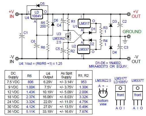
VG2 Enhanced
Virtual Ground
for Low Noise Audio Applications
|
 |
|
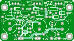
| VG2 PC Board (Top) |
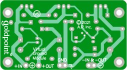
VG2 PC Board (Bottom) |
|
VG2 PC Boards are available for $8 each. - P/N = VG2
PC Board size: 1.4" x 2.55" - Mounting holes are for 4-40 screws, spaced 1.0" x 2.25". |
| All parts are redily available and easy to find - and can be ordered from Mouser.com
or Digikey.com. Resistor and
capacitor values
are not critical - you can substitute near or alternate values. |
|
VG2 Parts List:
|
notes:
|
| R1,
R2 - see VG2 schematic chart |
1/4W or 1/2W |
| R3,
R4 - 0.75 ohm to 1 ohm |
1/4W or 1/2W |
| R5 - 200 ohm |
1/4W or 1/2W
|
| R6 - see VG2 schematic chart |
1/4W or 1/2W |
| C1 - 470uF/50V** |
Panasonic
P/N EEU-FM1H471 |
| C2,
C3 - 1000uF/25V** |
Panasonic
P/N EEU-FM1E102 |
| C4,
C5, C6 - 22uF/50V |
Panasonic
P/N EEU-FM1H220 |
| D1 - D6 - 1N4002 (or
similar) |
for SMD: MMRA4003T3
|
| U1 -
LM317T |
TO-220
package Digi-Key, etc. |
| U2 -
LM337T |
TO-220
package Digi-Key, etc. |
| U3 -
LM336Z2.5 |
2.5V
voltage reference
(Fairchild) |
| U3 -
LD1084 or LD1085 |
TO-220
package Digi-Key, etc. |
|
|
|
Development
Credits:
|
Arn Roatcap:
(Founder of Goldpoint Level Controls goldpt.com
) - Prior to the LM317/LM337 circuits, built virtual grounds
using
fixed value voltage regulators (see circuits below). Integrated
new
ideas, constructed all of the prototypes and performed extensive
listening
tests. |
|
John
Broskie: (GlassWare glass-ware.com and Tube CAD tubecad.com
) - Suggested many virtual ground circuit ideas from 2006 to 2013.
Directed
the use of 1 ohm output resistors on the rail splitter voltage
regulators. |
|
Kim
Laroux: (head-fi.org
forums) - Had the ingenious idea to offset the
LM317/LM337
internal voltage references by using a single 2.5V zener diode. |
|
KT88:
(head-fi.org
forums) - Contributed the key idea to use a LM336 voltage reference,
instead
of a zener diode, to compensate the LM317/LM337 internal voltage
references. |
|
|
|
| Fixed Voltage Regulators |
Shown
here because of their simplicity, the following two circuits use fixed
value voltage regulators to split the rails. They MUST have
a third voltage regulator (U3) to keep the U1/U2 rail-to-rail voltage
from
going up or down. Some possible fixed value U3/U1/U2 voltage
regulator
combinations are:
[+10V, +5V,
-5V], [+12V, +6V, -6V], [+18V, +9V, -9V], [+24V,
+12V,
-12V]. |
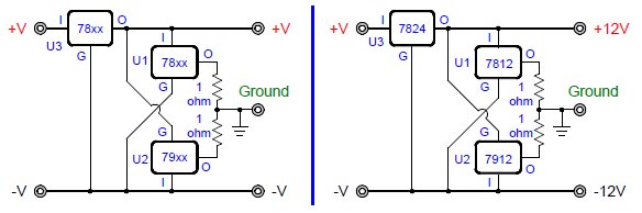
Basic
Virtual Ground
Circuit with Fixed Value Voltage Regulators
|
| When
a "complimentary pair" of fixed value voltage regulators are used to
create
a virtual ground this way, the absolute values of their output voltages
are each 1/2 of the rail-to-rail voltage. And the rail-to-rail
voltage must remain at a set, unvarying voltage which is the sum
of the absolute values of both of the rail splitter regulators output
voltages.
You therefore must use the third voltage regulator (U3). |
| Without
U3, the rail-to-rail voltage could go up or down with load changes,
battery drain, as the AC line voltage went up or down, etc. And if the
rail-to-rail voltage went up or down, the two fixed value regulators
would begin to compete with each other to establish different ground
points, one or both constantly wasting current (and possibly
overheating or burning up). So U3 is essential to ensure that fixed
value regulators U1 and U2 do not interact with each other. |
The
output of U3 needs to be close to the value of U1 added to the absolute
value of U2. As the output voltages of common fixed value voltage
regulators
vary by as much as 5% from their rated values, buying extra ones and
pre-testing
them to find their actual output voltages lets you select them to meet
the desired U3 = U1 + |U2|.
|
|
|
Because
U3 consumes twice as much power compared to U1 or U2, a good choice for
it is an adjustable voltage
regulator such as a 3 amp LD1085V or a 5 amp LD1084V. This also
gives the advantage
of allowing the use of any fixed value voltage regulators
for U1 and U2. With an adjustable regulator for U3, the virtual ground
point does not have to be centered between the rails. For example, you can make a
+5V/-12V power supply
by setting a variable voltage regulator U3 to 17V, selecting U1 as a
7805
(+5V), and U2 as a 7912 (-12V).
|
However, it is still a good idea to pre-test U1 and U2 to
find their actual
output voltages - then adjust the output voltage of U3 (via P1) to meet
the the desired U3 = U1 + |U2| before powering up.
|
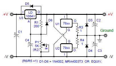
Virtual
Ground With Fixed
Value Voltage Regulators for Rail Splitter Section Only
|
An alternate way of setting P1
above to the correct voltage is as follows:
1) Set the ammeter on a high scale, such as the 10A scale.
2) Insert the ammeter in-line between the DC supply and the +V input.
3) Turn on the DC power supply.
4) Quickly adjust P1 to give the lowest quiescent current. If it
reads below 2A, change to the 2A scale.
If it is then seen to be below 200mA, (you're
aiming for perhaps 5mA to 50mA), switch to the 200mA scale.
5) Then use a voltmeter to test the output voltages relative to
the ground point. |
Alternatively,
you can replace P1 above with a fixed resistor (R2). This is even
recommended - if you already
know the exact voltages of U1 and U2. U3 = U1 + |U2|. The U3 output voltage = (R2/R1 +1) x 1.25. |
|
|
|
A
12V fixed value regulator
could operate as low as 11.5V or as high as 12.5V.
|
|
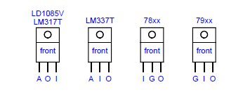
LD1085V:
Inexpensive ($1), adjustable, (1.25V to 28.5V), 3A positive, Low
Dropout
Voltage (LDO)
|
|
78xx
/ 79xx
(fixed) and LM317
/ LM337
(adjustable): Inexpensive (about $0.25) and commonly available.
|
|
|
|
|
A Power Op-Amp Virtual Ground Circuit
|
| Here
is a rail splitter virtual ground circuit which "works", but is a
second
or third choice sonically. While it does center the ground point
perfectly,
it requires a constant current source (the LD1085V) hung on its output
to sound any good when powering audio circuits. The constant current
source forces the power op-amp to run in class A mode. As both the
L165
and the LD1085V require heat sinks, this circuit is not good for
battery
use (too much wasted power). |
| The
L165 comes in a five lead TO-220 package, and is rated for up to 3 Amps
at +/-18V. |
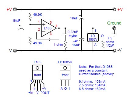
Power Opamp
Virtual Ground
Rail Splitter
|
|
|
|
|
|
Arn
Roatcap - Goldpoint Level Controls - (first
posted
20 August, 2012)
|
|